
3D map construction of coal mine roadway mobile robot based on integrated factor graph optimization
-
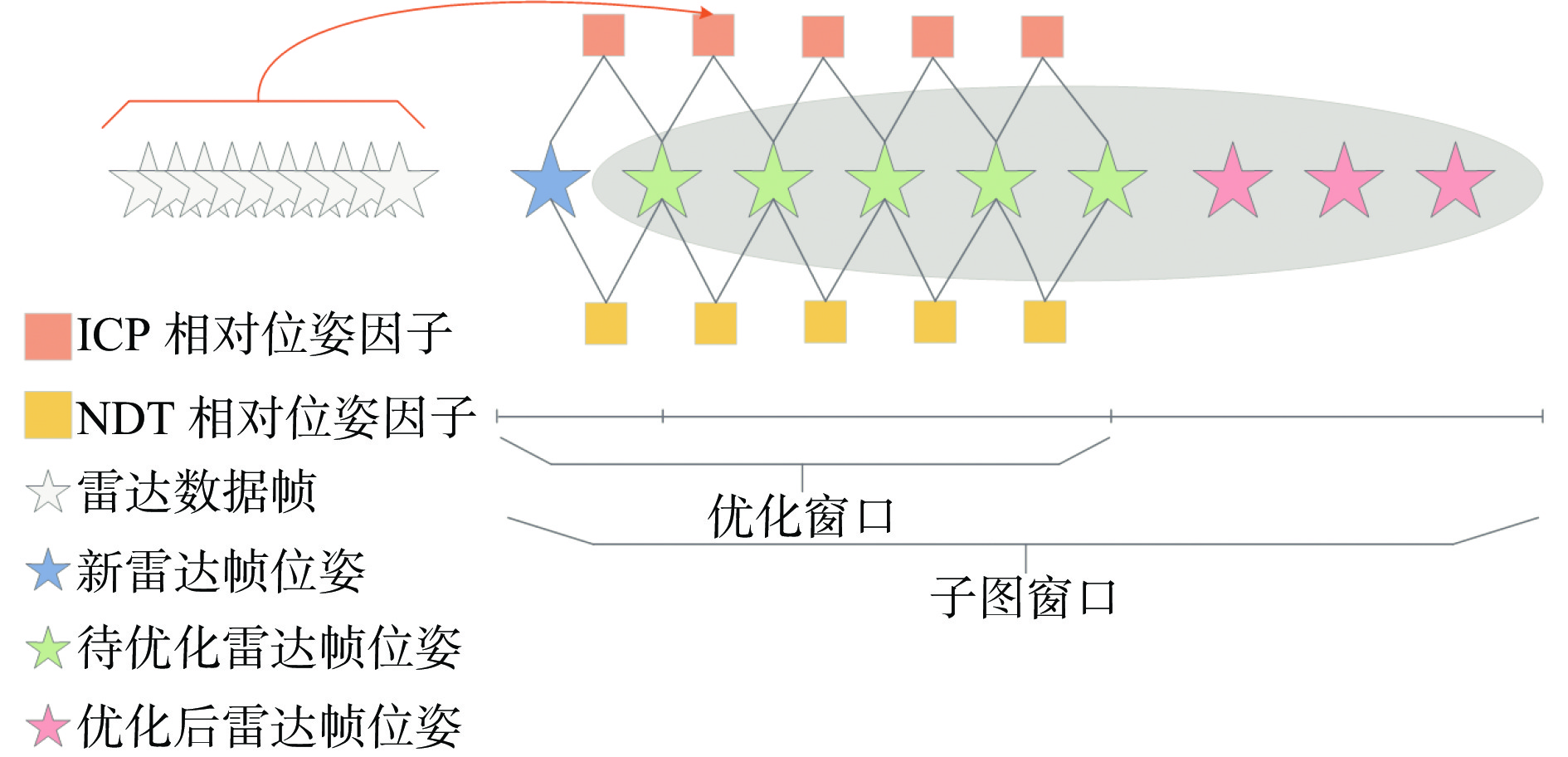
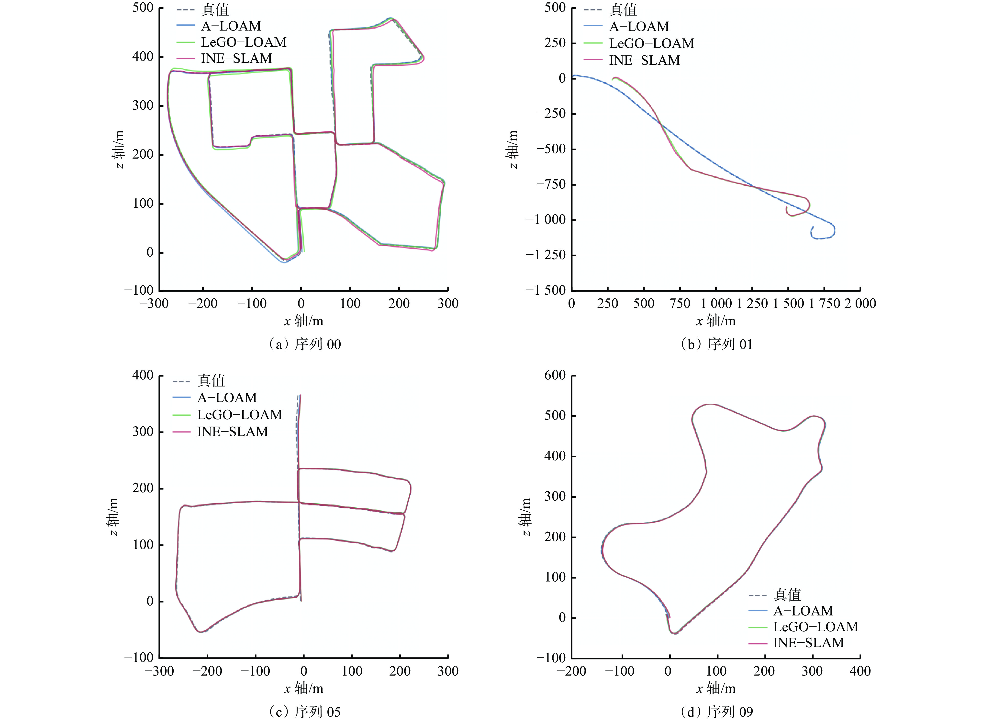
摘要: 煤矿井下移动机器人作业精度严重依赖于同步定位与建图 (SLAM) 技术的准确性。井下长直巷道存在特征缺失、光照条件差等问题,导致激光里程计和视觉里程计易失效,因而限制了传统SLAM方法在煤矿巷道的有效应用,且目前SLAM方法的研究主要聚焦于多传感融合建图方法,较少关注激光 SLAM 方法建图精度的提升。针对上述问题,面向移动机器人在煤矿巷道的建图需求,提出了一种基于集成式因子图优化的煤矿巷道移动机器人三维地图构建方法,采用前端构建和后端优化的策略,设计了前端点云配准模块和基于滤波、图优化的后端构建方法,使建图结果更准确、适应性更强。针对煤矿长直巷道环境退化导致三维激光点云配准精度低的问题,融合迭代最近点 (ICP) 和正态分布变换 (NDT)算法,兼顾点云几何特征和概率分布特征,设计了集成式前端点云配准模块,实现了点云的精确配准。针对三维激光 SLAM 后端优化问题,研究了基于位姿图和因子图优化的后端构建方法,构建了集成 ICP和NDT 相对位姿因子的因子图优化模型,以准确估计移动机器人位姿。分别利用公开数据集 KITTI和模拟巷道点云数据集对三维地图构建方法在不同工况下的性能进行了实验验证。公开数据集 KITTI上的实验结果表明:在全局一致性上,该方法与传统基于特征点匹配的A−LOAM方法和基于平面分割及特征点提取的LeGO−LOAM方法具有相似的性能,在建图局部精度上优于其他2种方法。模拟巷道点云数据集上的实验结果表明:该方法具有显著优势,通过因子图优化,可得到一致性较高的三维地图,提升了煤矿巷道三维地图构建的精度及鲁棒性,解决了井下长直巷道特征点缺失、激光里程计失效的难题。Abstract: The working precision of mobile robots in coal mines seriously depends on the accuracy of simultaneous localization and mapping (SLAM) technology. There are some problems such as feature missing and poor lighting conditions in long and straight underground roadway. The problems lead to the failure of the laser odometer and visual odometer. The result limits the effective application of traditional SLAM method in coal mine roadway. At present, the research of the SLAM method mainly focuses on the multi-sensor fusion mapping method. There is a lack of research on the improvement of the mapping precision of the laser SLAM method. In order to solve the above problems, facing the mapping requirements of mobile robot in coal mine roadway, a 3D map construction method of coal mine roadway mobile robot based on integrated factor graph optimization is proposed. The method adopts the strategy of front-end construction and back-end optimization. The method designs a front-end point cloud registration module and a back-end construction method based on filtering and graph optimization. Therefore, the mapping result is more accurate and adaptable. The environmental degradation in coal mine long and straight roadway leads to the low registration precision of 3D laser point cloud. In order to solve the above problem, integrating iterative closest point (ICP) and normal-distributions transform (NDT) algorithms, taking into account the geometric characteristics and probability distribution characteristics of point clouds, an integrated front-end point cloud registration module is designed, which realizes the accurate registration of point clouds. Inview of the back-end optimization problem of 3D laser SLAM, the back-end construction method based on pose map and factor map optimization is studied. The factor map optimization model integrating ICP and NDT relative pose factors is constructed to accurately estimate the pose of the mobile robot. The performance of the proposed method of 3D map construction under different working conditions is verified by using the open dataset KITTI and the simulated roadway point cloud dataset. The experimental results on the open dataset KITTI show the following points. In terms of global consistency, this method has similar performance with the traditional A-LOAM method based on feature point matching and the LeGO-LOAM method based on plane segmentation and feature point extraction. It is superior to the other two methods in the local precision of mapping. The experimental results on the simulated roadway point cloud dataset show the following points. This method has significant advantages, through factor map optimization, a 3D map with high consistency can be obtained. The precision and robustness of 3D map construction of coal mine roadway are improved. The problems of the feature point missing and laser odometer failure in long straight underground roadway are solved.
-
0. 引言
煤矿井下精确定位系统一般采用超宽带(Ultra-Wide Band,UWB)技术,其具有定位距离远、定位误差小、成本低等优点[1-3]。考虑到接收效率与覆盖范围等影响,当前配套的定位标志卡、矿灯等小型化无线终端设备主要使用全向天线[4-7]。然而,煤矿井下为受限空间,井巷结构狭长且断面较小,电磁波被限制在巷道内部传播,传播特性近似于矩形波导,多径效应突出,传播损耗大,通信距离短[8-10]。相比于定向天线的单向辐射模式,全向天线虽然具有更宽的覆盖范围,但是巷道壁的信号反射严重,能量损失大,多径效应明显,信号耦合效率低[11]。双向天线通过引导天线波束沿径向两端辐射,可有效提高信号覆盖范围和天线耦合效率,削弱由巷道侧壁反射所带来的多径效应,更加适用于结构狭长、断面较小的煤矿井下巷道。
双向天线可由2个背靠背的八木天线实现[12]。此外,将同相激励的偶极子组阵也可实现双向辐射[13]。文献[14]提出的Bruce阵列采用同相磁流激励,具有高增益双向辐射特性。文献[15-16]将环形天线级联,设计了适用于煤矿巷道环境的双向辐射天线。上述天线均通过组阵方式形成端射/边射双向波束。煤矿应用环境对阵列天线的规模、尺寸、材质等都有特殊要求,一般的双向阵列天线原理和技术不能直接应用于井下无线终端设备。文献[17]提出了一种双向辐射的超宽带等角螺旋天线,其缺点是剖面过大,且天线增益偏低。文献[18]通过在有限大金属地板上开槽,激励出缝隙磁流辐射模式,以产生双向波束,但其尺寸仍然偏大。文献[19]将2个辐射贴片相对开槽地板背靠背排列,在水平面激励出了双向波束,其缺点是带宽过窄,无法满足井下UWB精确定位系统对带宽的要求。
针对上述问题,本文设计了一种小型化双向波束矿用定位终端天线。通过布置2个间距为λ/4 (λ为自由空间波长)的同相激励U形单极子天线,实现双向边射波束辐射特性。此外,通过地板开槽的方式实现天线的小型化。该天线在保证整体结构紧凑的同时兼顾了净空区面积,天线模块占用电路板面积小,方便其他电路布局,适用于各类小型化人员定位终端设备。
1. 天线设计
1.1 天线结构
小型化双向波束矿用定位终端天线由2个U形辐射振子、带有2个U形槽的金属地板和馈电网络组成,并经由2块FR−4介质基板(相对介电常数为4.3,损耗角正切为0.02)压合而成,如图1所示。xyz为基于天线形状构建的坐标系,H1,H2为介质基板厚度;S1为两个单极子间距;S2为两个U形槽间距;S3为U形槽与微带馈线间距;S4为U形槽张口尺寸;G1、G2分别为介质基板的长与宽;Wf1-Wf3为微带馈线的宽度;Ls1、Ls2为U形槽长度;La1-La3为U形单极子长度;Ws1为U形槽的宽度;Wa1-Wa4为U形单极子宽度;g为U形单极子与地板间距。天线采用50 Ω微带线馈电,通过1个功分馈电网络经由金属通孔与U形辐射振子相连。天线尺寸参数见表1。
![]() 图 1 小型化双向波束矿用定位终端天线结构Figure 1. Structure of the miniaturized bidirectional beam mine positioning terminal antenna表 1 天线尺寸参数Table 1. Antenna dimension parameters
图 1 小型化双向波束矿用定位终端天线结构Figure 1. Structure of the miniaturized bidirectional beam mine positioning terminal antenna表 1 天线尺寸参数Table 1. Antenna dimension parametersmm 参数 尺寸 参数 尺寸 参数 尺寸 H1 0.45 Wf1 0.36 Ws1 0.5 H2 0.2 Wf2 0.6 Ws2 1.88 S1 11.5 Wf3 0.36 Wa1 1.48 S2 5 Ls1 5.5 Wa2 0.7 S3 8.6 Ls2 5.75 Wa3 1.2 S4 4.75 La1 5.5 Wa4 2.7 G1 25 La2 5.7 g 0.4 G2 25 La3 3.05 1.2 双向波束原理
根据阵列天线理论,沿直线等距离排列的n个等幅激励各向同性点源(图2),当阵因子达到最大值时,在远场所辐射的主瓣波束方向上,产生阵因子主瓣最大值所需相邻阵元之间的激励电流相移为[20]
$$ \delta =-\frac{2\text{π}d}{\lambda }\cos \varphi $$ (1) 式中:d为相邻阵元的间距;$ \varphi $为远场所辐射的主瓣波束与各向同性点源直线阵之间的夹角。
对于边射阵,即$\varphi $=90°,此时δ=0;对于端射阵,即$\varphi $=0,此时$ \delta =-\dfrac{2{\text{π}} d}{\lambda } $。为了缩小天线尺寸和节约电路板面积,本文选择边射阵,即相邻阵元采用等幅同相馈电方式。对于边射阵,在不考虑阵元间互耦的前提下,阵元间距d取值大小只与增益相关。考虑到现有矿用定位终端设备(如定位标志卡、腕卡、矿灯)的实际大小及未来的小型化趋势,选取阵元数量n=2,间距d=λ/4。
1.3 设计过程
当前矿井人员和UWB定位系统中采用的主流UWB芯片为DW1000,其中心工作频率包括3.5,4.0,4.5,6.5 GHz。为了有效提升传输距离,降低与5G、WiFi6等通信系统频段间的相互干扰,并减少基站部署数量及系统整体成本,目前矿用UWB频段多为3.7~4.2 GHz[21]。参照现有各类基于UWB技术的矿用定位终端设备尺寸规格,并鉴于此类设备小型化及便携性的发展趋势,其搭载的终端定位天线亦需具备尺寸小、结构简单及易于集成等特性。
天线设计过程如图3所示。
将单极子作为基本天线单元,搭载于一块25 mm×25 mm的FR−4介质基板上,记为天线Ⅰ(图3(a))。为了缩小天线尺寸,节约净空区面积并拓展带宽,天线采用U形弯折结构,其总长度约为λ/4(4.1 GHz),其各枝节长度与宽度在尽可能保证较低净空区高度前提下,借助全波电磁仿真软件CST Studio Suite 2018进行建模分析并优化。受限于较小的地板尺寸(0.33λ× 0.24λ),天线Ⅰ的阻抗匹配较差,反射系数较大。为了实现边射双向波束,将U形单极子在x轴方向平移约λ/4(17 mm)并镜像复制,得到天线Ⅱ(图3(b))。
对2个U形单极子单元施加等幅同相激励,得到沿±z轴方向辐射的双向波束。其反射系数如图4所示。受益于U形单极子在x轴方向的平移,辐射臂相对于金属地板不再呈中心对称,因此天线带宽得到了拓宽,−10 dB相对带宽达25%。此外,由于2个天线间距较近,相互耦合强烈,天线Ⅱ的工作频点向高频发生了偏移。
为了降低天线Ⅱ的工作频率,且不扩大单极子振子臂及金属地板的尺寸,在金属地板上开设2个对称的U形槽,得到天线Ⅲ(图3(c))。U形槽初始总长度约为λ/4(4.1 GHz),借助全波电磁仿真软件进行调谐,从而起到降低天线Ⅱ谐振频率的效果。
天线Ⅱ和天线Ⅲ工作时表面电流分布如图5所示。通过在地板上引入U形槽,在槽缝处形成了额外的缝隙耦合电流,相较于天线Ⅱ,天线Ⅲ的地板电流路径得到了延长,从而有效降低了天线工作频点。
![]() 图 5 天线II和III工作时表面电流分布Figure 5. Surface current distribution of antennas II and III in operation
图 5 天线II和III工作时表面电流分布Figure 5. Surface current distribution of antennas II and III in operation结合图4可知,增加U形槽后,天线工作频点降至4 GHz,带宽相比天线Ⅱ有所减小,但仍能有效覆盖当前矿用UWB频段(3.7~4.2 GHz)。需要指出的是,天线Ⅱ与Ⅲ中天线单元均由离散端口单独馈电,因此图4所示为天线Ⅱ与Ⅲ的有源反射系数。
最后,以天线Ⅲ为基础,设计了一个等幅同相功分馈电网络,用于给2个U形单极子天线馈电,记作天线Ⅳ(图3(d))。天线Ⅳ的中心频点为4.1 GHz,−10 dB带宽为3.6~4.6 GHz。
2. 仿真分析
天线3D远场辐射方向图、2D远场辐射方向图分别如图6、图7所示。可看出二元边射阵在±z轴方向实现了双向辐射波束,远场辐射方向图关于xoy平面对称。E面(yoz面)1 dB波束宽度为56°,H面(xoz面)1 dB波束宽度为70°。
二元边射阵峰值增益随频率变化的仿真结果如图8所示。可看出在3.6~4.6 GHz频段范围内,天线的峰值增益范围为2.2~2.5 dBi,体现出良好的幅频响应。
3. 实测结果及分析
天线实物由3层金属经由2块FR−4介质基板按图1(a)所示顺序压合而成,制备样品如图9所示。其中上层介质基板厚度为0.45 mm,下层介质基板厚度为0.2 mm,从上至下分别为U形辐射臂、金属地板、馈电网络。天线整体尺寸为0.3λ×0.3λ×0.01λ(长×宽×高),净空区尺寸为0.3λ×0.1λ(长×宽)。
天线由一个50 Ω的SMA接头馈电,并通过矢量网络分析仪Keysight E5063A测量反射系数,结果如图10所示。可看出天线实测−10 dB阻抗带宽为3.52~4.65 GHz,与仿真结果基本吻合。二者的偏差主要源于FR−4介质基板的介电常数波动及SMA接头焊接所引起的阻抗失配。
![]() 图 10 反射系数仿真与实测对比Figure 10. Comparison between simulated and measured reflection coefficient
图 10 反射系数仿真与实测对比Figure 10. Comparison between simulated and measured reflection coefficient在Satimo SG 24探针近场微波暗室中进行天线方向图测试,结果如图11所示。在工作中心频点附近(4 GHz),天线实测E面(yoz面)1 dB波束宽度为53°,H面(xoz面)1 dB波束宽度为64°。
![]() 图 11 2D远场辐射方向图仿真与实测对比Figure 11. Comparison between simulated and measured 2D far-field radiation pattern
图 11 2D远场辐射方向图仿真与实测对比Figure 11. Comparison between simulated and measured 2D far-field radiation pattern峰值增益−频率仿真与实测结果对比如图12所示。可看出仿真与实测结果基本相符,在3.6~4.6 GHz频段内,天线峰值增益范围为2.1~2.45 dBi。
![]() 图 12 峰值增益−频率仿真与实测结果对比Figure 12. Comparison between simulated and measured peak gain over frequency
图 12 峰值增益−频率仿真与实测结果对比Figure 12. Comparison between simulated and measured peak gain over frequency实测天线的−10 dB带宽为1 000 MHz (3.6~4.6 GHz),可有效覆盖基于UWB的煤矿井下人员精确定位系统的工作频段(3.7~4.2 GHz)。
4. 结语
设计了一种小型化双向波束矿用定位终端天线,以U形单极子天线为基础,通过布置2个间距为λ/4的等幅同相激励阵元,实现了双向边射波束辐射特性。天线实测与仿真结果吻合良好,在3.6~4.6 GHz频段内,天线峰值增益范围为2.1~2.45 dBi;天线的−10 dB带宽为1 000 MHz (3.6~4.6 GHz),可有效覆盖基于UWB的煤矿井下人员精确定位系统的工作频段。该天线具有结构紧凑、净空区面积小、成本低廉等优点,适用于各类小型化人员定位终端设备,具有很好的潜在应用价值。
-
![]()
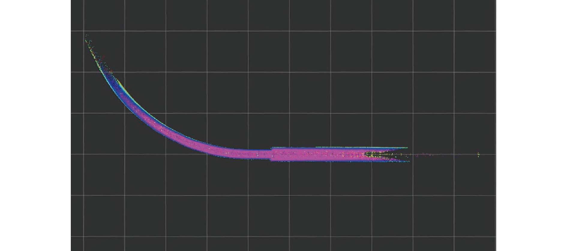
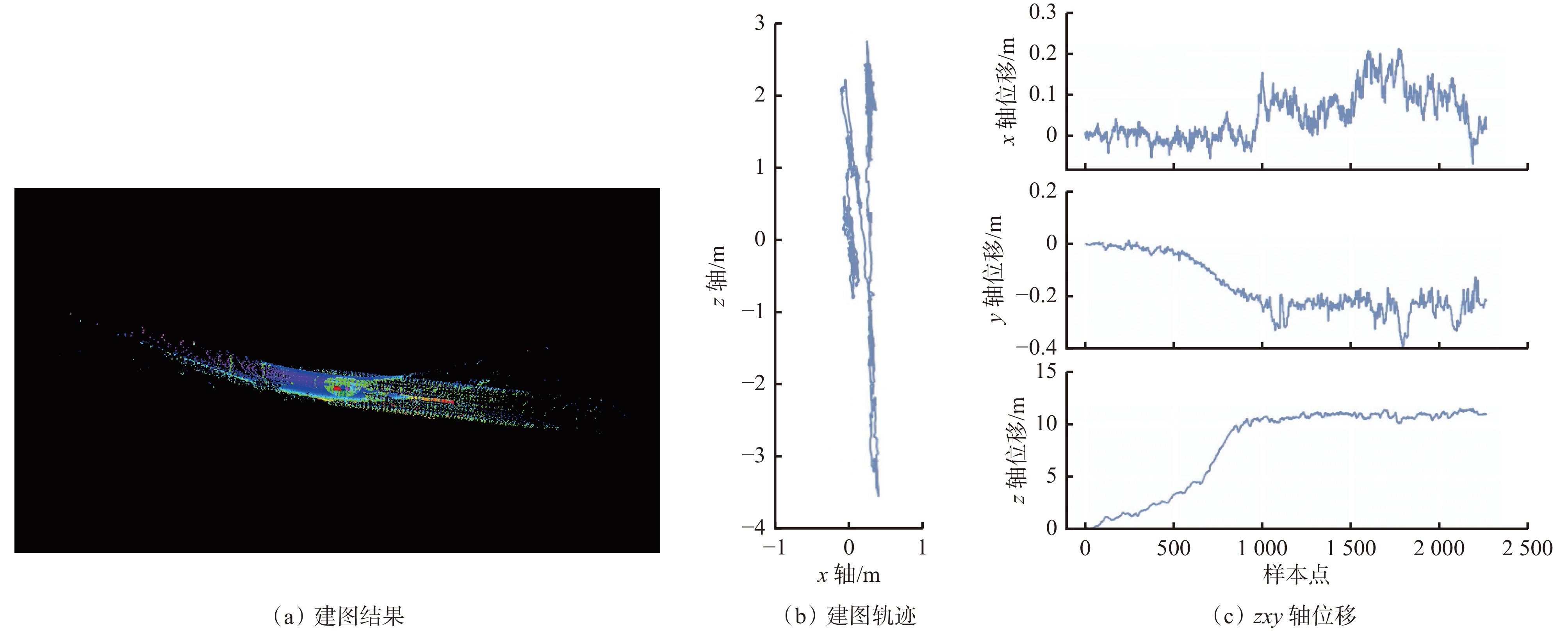
图 7 INE−SLAM方法在模拟巷道的建图效果
Figure 7. Mapping effect of ICP and NDT ensemble SLAM in simulated roadway
![]()
图 8 LeGO−LOAM 方法在模拟巷道的建图结果
Figure 8. Mapping result of lightweight and ground-optimized LOAM in simulated roadway
![]()
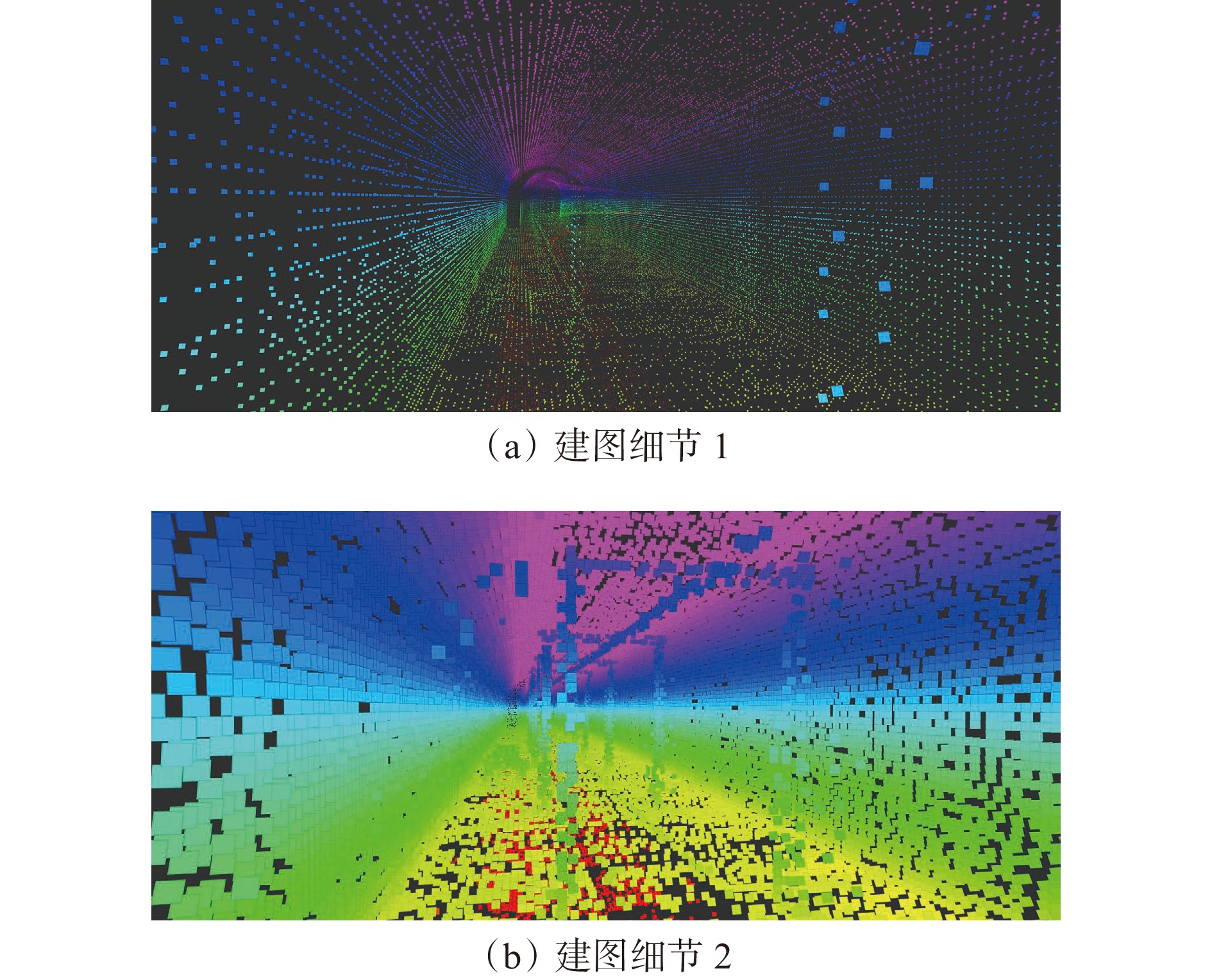
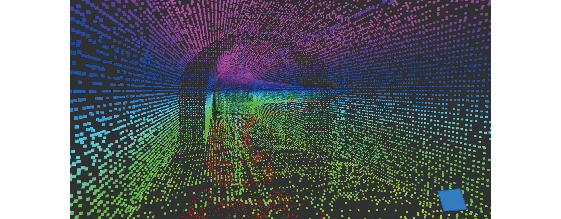
图 10 巷道收窄部分INE−SLAM 方法的建图细节
Figure 10. Mapping details of ICP and NDT ensemble SLAM in narrowing roadway
表 1 APE对比
Table 1 Absolute pose error comparison
序列 方法 APE/m 最大值 平均值 中位数 最小值 均方根误差 和方差 标准偏差 A−LOAM 7.708074 2.014421 1.705119 0.291645 2.465952 27558.715930 1.422330 00 LeGO−LOAM 8.557403 4.429299 4.409769 0.351308 4.866022 107309.456000 2.014814 INE−SLAM 17.083902 7.400451 7.140376 0.808981 8.020236 291517.204500 3.091523 A−LOAM 35.109976 16.999973 18.074131 0.728562 18.893051 391928.228800 8.243076 01 LeGO−LOAM 290.476267 201.358024 224.237243 113.022321 210.274942 48548675.320000 60.584632 INE−SLAM 297.638420 203.560376 226.902531 112.478793 212.970114 49801183.740000 62.605453 A−LOAM 8.140921 1.971348 1.592937 0.228409 2.373178 15527.353030 1.321272 05 LeGO−LOAM 9.238267 2.139186 1.827800 0.482764 2.519107 17495.642090 1.330332 INE−SLAM 8.649879 2.256443 1.996284 0.472615 2.514627 17433.470720 1.109870 A−LOAM 3.285654 1.331722 1.012147 0.242015 1.545941 3795.214464 0.785143 09 LeGO−LOAM 6.063340 2.108868 1.971362 0.292446 2.343031 8717.794097 1.021015 INE−SLAM 7.315510 2.622855 2.616781 0.112678 2.840584 12813.436660 1.090663  下载: 导出CSV
表 2 RPE对比
Table 2 Relative pose error comparison
序列 方法 RPE/m 最大值 平均值 中位数 最小值 均方根误差 和方差 标准偏差 A−LOAM 1.896651 1.154897 1.200041 0.003222 1.215805 6697.636647 0.379992 00 LeGO−LOAM 0.972212 0.061612 0.047549 0.003754 0.076631 26.607482 0.045567 INE−SLAM 0.514520 0.092929 0.078107 0.004084 0.109881 54.707031 0.058635 A−LOAM 3.885951 3.132486 3.553323 1.028025 3.218495 11363.507790 0.739085 01 LeGO−LOAM 2.699271 0.517959 0.169555 0.016541 0.831417 758.306416 0.650364 INE−SLAM 2.604537 0.517871 0.170409 0.020407 0.831250 758.001303 0.650220 A−LOAM 1.716019 1.123840 1.217291 0.000759 1.196405 3944.896806 0.410327 05 LeGO−LOAM 0.942990 0.053947 0.046318 0.002914 0.063128 10.983231 0.032786 INE−SLAM 0.883468 0.056378 0.047659 0.003852 0.065977 11.996595 0.034271 A−LOAM 2.197394 1.505677 1.491705 0.323694 1.550710 3816.262265 0.370999 09 LeGO−LOAM 0.334782 0.063748 0.057174 0.005735 0.070704 7.933544 0.030582 INE−SLAM 0.315042 0.064674 0.058037 0.008362 0.071649 8.146901 0.030836
下载: 导出CSV
-
[1] 杨林,马宏伟,王岩,等. 煤矿巡检机器人同步定位与 地图构建方法研究[J]. 工矿自动化,2019,45(9):18-24. YANG Lin,MA Hongwei,WANG Yan,et al. Research on method of simultaneous localization and mapping of coal mine inspection robot[J]. Industry and Mine Automation,2019,45(9):18-24.
[2] 孙继平,江嬴. 矿井车辆无人驾驶关键技术研究[J]. 工矿自动化,2022,48(5):1-5,31. DOI: 10.13272/j.issn.1671-251x.17947 SUN Jiping,JIANG Ying. Research on key technologies of mine unmanned vehicle[J]. Journal of Mine Automation,2022,48(5):1-5,31. DOI: 10.13272/j.issn.1671-251x.17947
[3] 潘祥生,陈晓晶. 矿用智能巡检机器人关键技术研究[J]. 工矿自动化,2020,46(10):43-48. DOI: 10.13272/j.issn.1671-251x.2020080042 PAN Xiangsheng,CHEN Xiaojing. Research on key technologies of mine-used intelligent inspection robot[J]. Industry and Mine Automation,2020,46(10):43-48. DOI: 10.13272/j.issn.1671-251x.2020080042
[4] 周治国,曹江微,邸顺帆. 3D 激光雷达 SLAM 算法综述[J]. 仪器仪表学报,2021,42(9):13-27. ZHOU Zhiguo,CAO Jiangwei,DI Shunfan. Overview of 3D Lidar SLAM algorithms[J]. Chinese Journal of Scientific Instrument,2021,42(9):13-27.
[5] ZHANG Ji, SINGH S. LOAM: lidar odometry and mapping in real-time[C]. Robotics: Science and Systems Conference, Berkeley, 2014. DOI: 10.15607/RSS. 2014.X.007.
[6] HESS W, KOHLER D, RAPP H, et al. Real-time loop closure in 2D LIDAR SLAM[C]. IEEE International Conference on Robotics and Automation (ICRA) , Stockholm, 2016: 1271-1278.
[7] SHAN Tixiao, ENGLOT B. LeGO-LOAM: lightweight and ground-optimized lidar odometry and mapping on variable terrain[C]. IEEE/RSJ International Conference on Intelligent Robots and Systems (IROS), Madrid, 2018: 4758-4765.
[8] SHAN Tixiao, ENGLOT B, MEYERS D, et al. LIO-SAM: tightly-coupled lidar inertial odometry via smoothing and mapping[C]. IEEE/RSJ International Conference on Intelligent Robots and Systems (IROS), Madrid, 2020: 3106-3111.
[9] BESL P J,MCKAY N D. A method for registration of 3D shapes[J]. IEEE Transactions on Pattern Analysis and Machine Intelligence,1992,14(2):239-256. DOI: 10.1109/34.121791
[10] LI Qingde ,GRIFFITHS J G. Iterative closest geometric objects registering[J]. Computers & Mathematics with Applications,2000,40(10/11):1171-1188.
[11] CHEN Hui, BHANU B. Contour matching for 3D ear recognition[C]. 7th IEEE Workshop on Applications of Computer Vision, Breckenridge, 2005: 123-128.
[12] HE Shijun, ZHAO Shiting, BAI Fan, et al. A method for spatial data registration based on PCA-ICP algorithm[C]. 3rd International Conference on Advanced Measurement and Test, Xiamen, 2013: 1063-1066.
[13] BIBER P, STRASSER W. The normal distributions transform: a new approach to laser scan matching[C]. IEEE/RSJ International Conference on Intelligent Robots and Systems (IROS), Las Vegas, 2003: 2743-2748.
[14] KOIDE K,MIURA J,MENEGATTI E. A portable three-dimensional LIDAR-based system for long-term and wide-area people behavior measurement[J]. International Journal of Advanced Robotic Systems,2019,16(2):1729-8806.
[15] LI Menggang,ZHU Hua,YOU Shaoze,et al. Efficient laser-based 3D SLAM for coal mine rescue robots[J]. IEEE Access,2019,7:14124-14138. DOI: 10.1109/ACCESS.2018.2889304
[16] XU Jiachang,HUANG Yourui,ZHAO Ruijuan,et al. Probabilistic membrane computing-based SLAM for patrol UAVs in coal mines[J]. Journal of Sensors,2021:1-11. DOI: 10.1155/2021/7610126.
[17] 王佳婧,王晓南,郑顺义,等. 三维点云初始配准方法的比较分析[J]. 测绘科学,2018,43(2):16-23. DOI: 10.16251/j.cnki.1009-2307.2018.02.004 WANG Jiajing,WANG Xiaonan,ZHENG Shunyi,et al. Comparison and analysis of initial registration methods of 3D point cloud[J]. Science of Surveying and Mapping,2018,43(2):16-23. DOI: 10.16251/j.cnki.1009-2307.2018.02.004
[18] 李猛钢. 煤矿救援机器人导航系统研究[D]. 徐州: 中国矿业大学, 2017. LI Menggang. Research on navigation system of coal mine rescue robot [D]. Xuzhou: China University of Mining and Technology, 2017.
[19] SCHULZ C, ZELL A. Real-time graph-based SLAM with occupancy normal distributions transforms [C]. IEEE International Conference on Robotics and Automation (ICRA), Paris, 2020: 3105-3111.
[20] PARK C, MOGHADAM P, KIM S, et al. Elastic LiDAR fusion: dense map-centric continuous-time SLAM[C]. IEEE International Conference on Robotics and Automation (ICRA), Brisbane, 2018: 1-25.
[21] QIN Chao, YE Haoyang, PRANATA C E, et al. LINS: a lidar-inertial state estimator for robust and efficient navigation[C]. IEEE International Conference on Robotics and Automation (ICRA), Paris, 2020: 8899-8906.
[22] KSCHISCHANG F,FREY B,LOELIGER H. Factor graphs and the sum-product algorithm[J]. IEEE Transactions on Information Theory,2001,47(2):498-498. DOI: 10.1109/18.910572
[23] KUMMERLE R, GRISETTI G, STRASDAT H, et al. G2o: a general framework for graph optimization[C]. IEEE International Conference on Robotics and Automation, Shanghai, 2011: 3607-3613.
[24] KAESS M,DELLAERT F. iSAM:incremental smoothing and mapping[J]. IEEE Transactions on Robotics,2008,24(6):1365-1378.
[25] KAESS M, JOHANNSSON H, ROBERTS R, et al. iSAM2: incremental smoothing and mapping with fluid relinearization and incremental variable reordering[C]. IEEE International Conference on Robotics and Automation, Shanghai, 2011. DOI: 10.1109/ICRA.2011.5979641.
[26] DELLAERT F. Factor graphs and GTSAM: a hands-on introduction [EB/OL]. (2016-01-13) [2022-09-16]. https://www.docin.com/p-1444792601.html.
[27] GEIGER A,LENZ P,STILLER C,et al. Vision meets robotics:the KITTI dataset[J]. The International Journal of Robotics Research,2013,32(11):1231-1237. DOI: 10.1177/0278364913491297


计量
- 文章访问数: 379
- HTML全文浏览量: 212
- PDF下载量: 56
