
Coordinated optimization method for IGBT peak voltage suppression of mine-used inverter
-
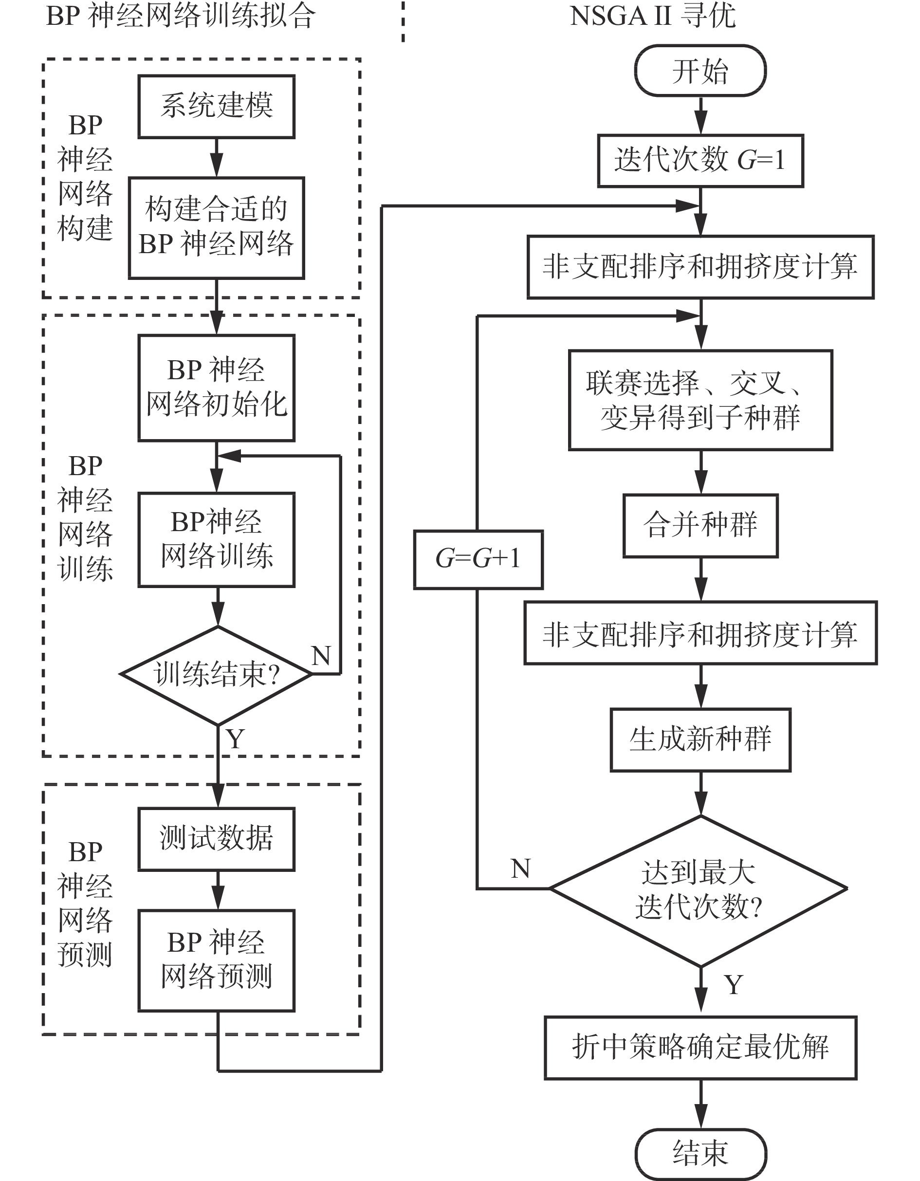
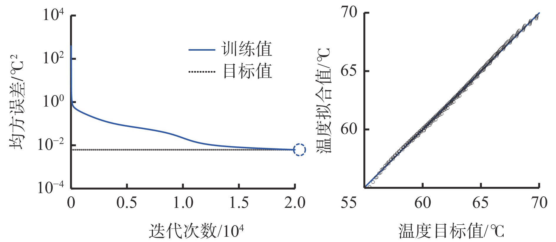
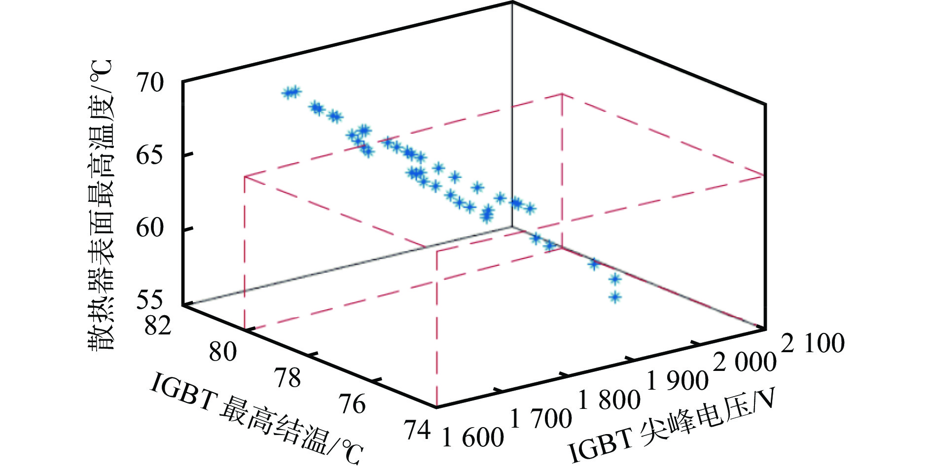
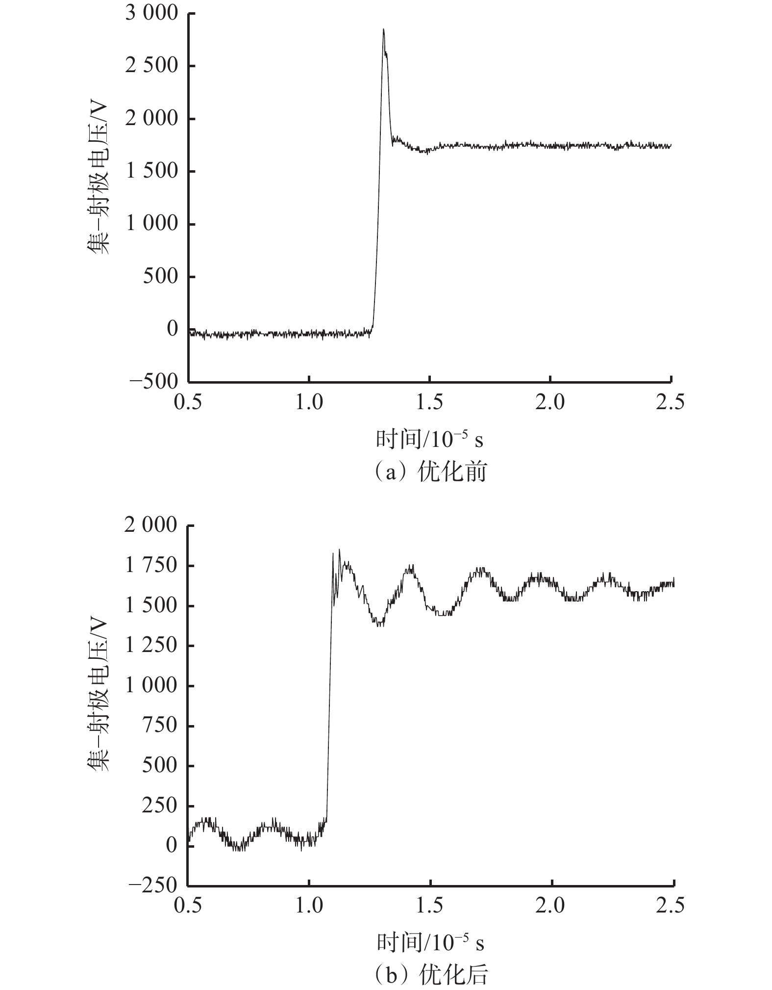
摘要: 目前常用优化母排结构参数、改变栅极驱动电阻、设计吸收电路等方法抑制因杂散电感引起的矿用变频器中绝缘栅双极型晶体管(IGBT)尖峰电压,但现有研究未揭示各方法之间的协调统一关系及协调优化准则。针对该问题,以BPJ5−630−1140型矿用四象限变频器为研究对象,在分析杂散电感对IGBT电−热性能影响的基础上,提出了IGBT尖峰电压抑制的协调优化方法:① 分析母排结构参数、栅极驱动电阻对IGBT尖峰电压和功率损耗的影响,结果表明,随着交流母排长度增大、宽度减小,IGBT尖峰电压和功率损耗均增大;随着栅极驱动电阻增大,IGBT尖峰电压减小,功率损耗增大。② 设计二极管钳位式吸收电路,通过试验验证了该电路可降低IGBT尖峰电压和功率损耗。③ 考虑到交流母排宽度对IGBT布局和散热性能无影响,选择栅极驱动电阻和交流母排长度为决策变量,采用BP神经网络−带精英策略的非支配排序遗传算法(BP−NSGAⅡ)实现IGBT尖峰电压、最高结温及散热器表面最高温度的多目标极值寻优。试验结果表明:在散热器表面最高温度为55~65 ℃、IGBT最高结温为74~80 ℃时,IGBT 尖峰电压最小值为1 861 V,相应的栅极驱动电阻为5 Ω,交流母排长度为300 mm、宽度为200 mm;优化后BPJ5−630−1140型变频器IGBT尖峰电压为1 856 V,较优化前的2 856 V降低了35%,有效抑制了IGBT尖峰电压,提高了矿用变频器运行可靠性。
-
关键词:
- 矿用变频器 /
- 绝缘栅双极型晶体管 /
- 尖峰电压抑制 /
- 栅极驱动电阻 /
- 二极管钳位式吸收电路 /
- BP神经网络−带精英策略的非支配排序遗传算法
Abstract: At present, the methods of optimizing busbar structure parameters, changing gate drive resistance and designing absorption circuit are commonly used to suppress the peak voltage of insulated gate bipolar transistor (IGBT) in mine-used inverter caused by stray inductance. But the existing research has not revealed the coordination and unification relationship between the methods and their coordination and optimization criteria. In order to solve this problem, taking BPJ5-630-1140 type mine-used four-quadrant inverter as the research object, based on the analysis of the influence of stray inductance on the electric-thermal performance of IGBT, a coordinated optimization method of IGBT peak voltage suppression is proposed. ① The method analyzes the influence of busbar structure parameters and grid drive resistance on IGBT peak voltage and power loss. The results show that the peak voltage and power loss of IGBT increase with the AC busbar length increase and the AC busbar width decrease. With the increase of gate drive resistance, IGBT peak voltage decreases and power loss increases. ② The diode clamped absorption circuit is designed, which is verified by experiments to reduce the peak voltage and power loss of IGBT. ③ Considering that the AC busbar width has no effect on the layout and heat dissipation performance of IGBT, the gate drive resistance and the AC busbar length are selected as decision variables. The BP neural network and elitist non-dominated sorting genetic algorithm (BP-NSGAⅡ) are used to achieve multi-objective optimization of IGBT peak voltage, the maximum IGBT temperature and the maximum temperature of radiator surface. The experimented results show that when the maximum temperature of radiator surface is 55-65 ℃ and the maximum IGBT temperature is 74-80 ℃, the minimum IGBT peak voltage is 1861 V. The corresponding grid drive resistance is 5 Ω, the AC busbar length is 300 mm, and the AC busbar width is 200 mm. The optimized IGBT peak voltage of BPJ5-630-1140 type inventer is 1 856 V, which is 35% lower than 2 856 V before optimization. The IGBT peak voltage is effectively suppressed, and the operation reliability of the mine-used inverter is improved. -
-
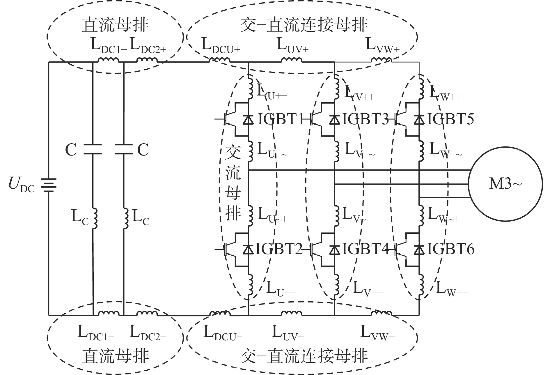
![]()
图 1 考虑杂散电感的矿用变频器主电路拓扑等效模型
Figure 1. Equivalent model of main circuit topology of mine-used inverter considering stray inductance
![]()
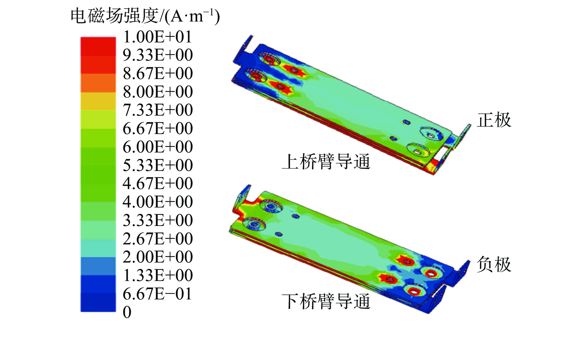
图 2 交流母排电磁场强度分布云图
Figure 2. Distribution cloud chart of electromagnetic field intensity of AC busbar
![]()
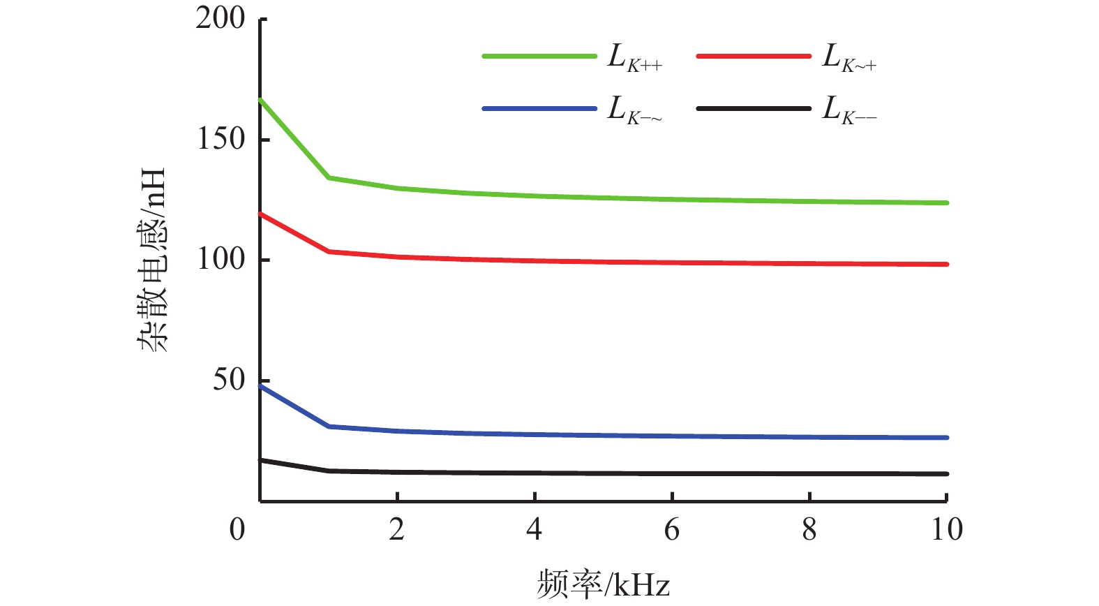
图 3 交流母排杂散电感随激励频率变化曲线
Figure 3. Variation curves of stray inductance in AC busbar with excitation frequency
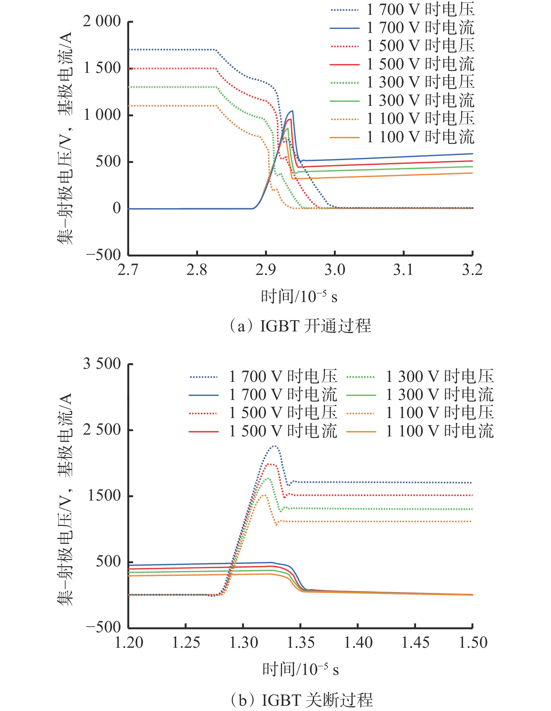
![]()
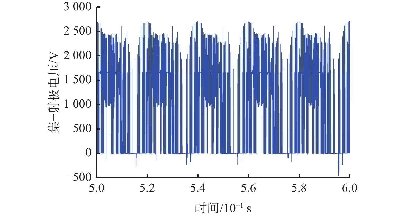
图 4 满载工况下IGBT集−射极电压波形
Figure 4. Collector-emitter voltage waveform of IGBT under full load condition
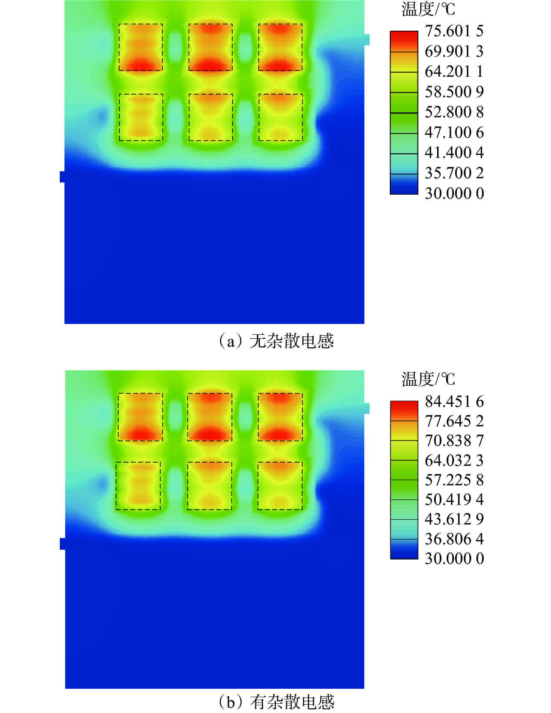
![]()
图 6 IGBT及水冷散热器温度云图
Figure 6. Temperature cloud chart of IGBT and water-cooled radiator
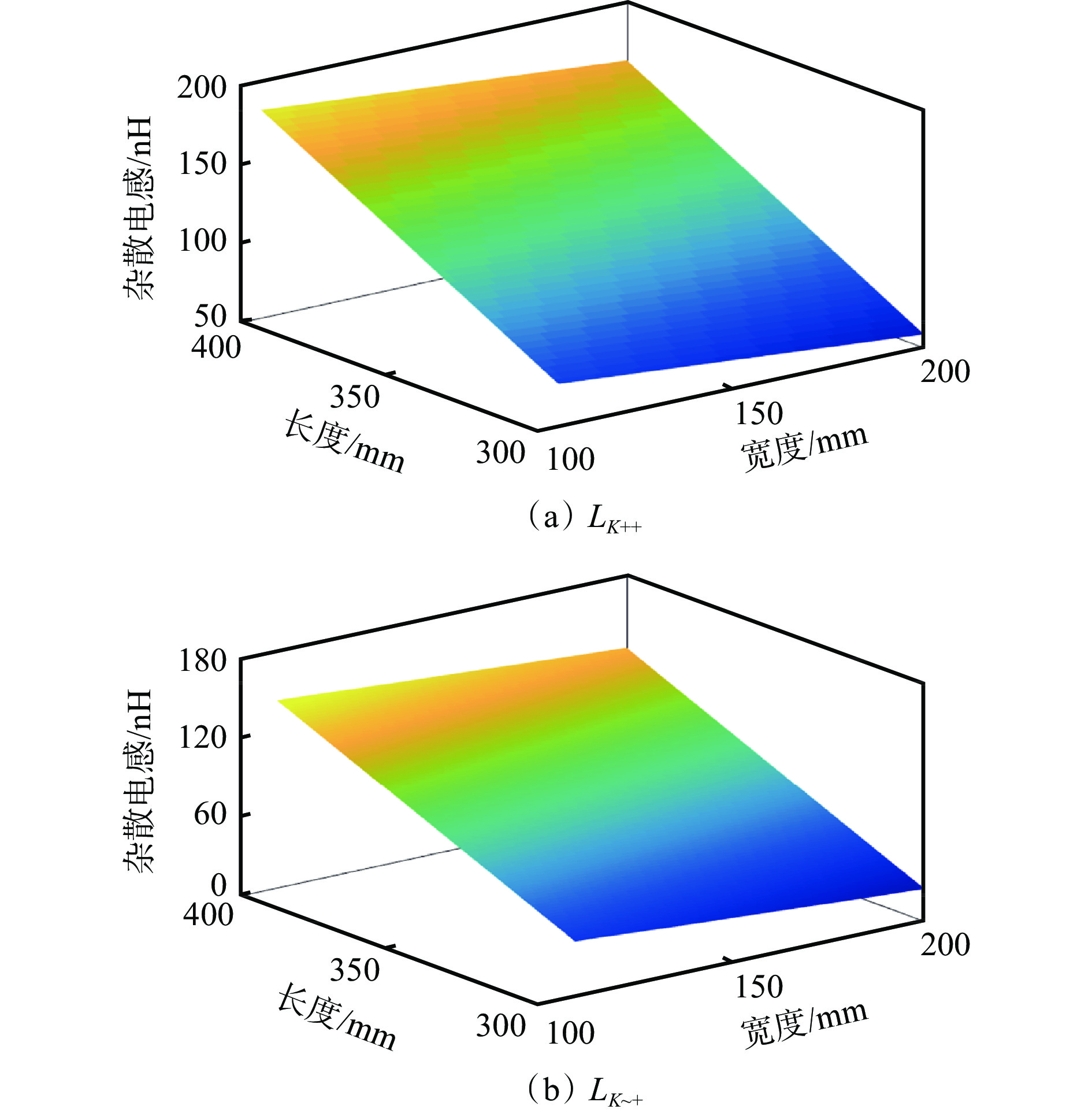
![]()
图 8 交流母排长度、宽度与杂散电感对应关系
Figure 8. Corresponding relationship between AC busbar length or width and stray inductance
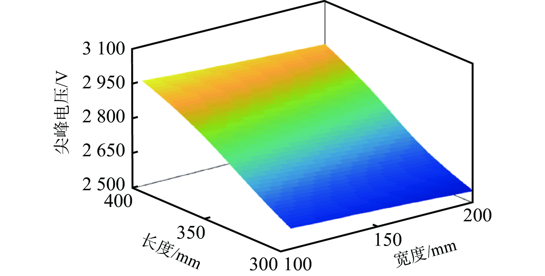
![]()
图 9 交流母排长度、宽度与IGBT尖峰电压的对应关系
Figure 9. Corresponding relationship between AC busbar length or width and IGBT peak voltage
![]()
图 10 交流母排长度、宽度与IGBT功率损耗的对应关系
Figure 10. Corresponding relationship between AC busbar length or width and IGBT power loss
![]()
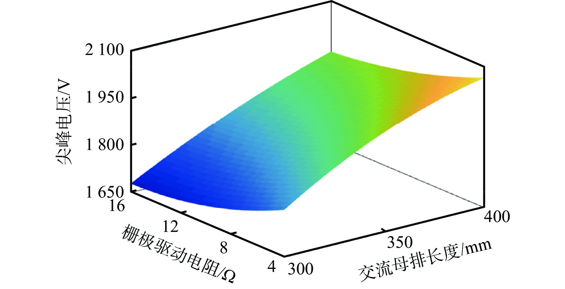
图 11 栅极驱动电阻、交流母排长度与IGBT尖峰电压的对应关系
Figure 11. Corresponding relationship between gate drive resistance or AC busbar length and IGBT peak voltage
![]()
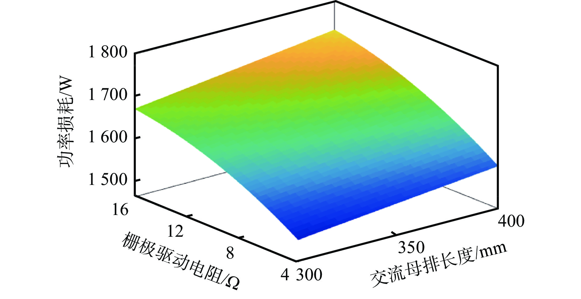
图 12 栅极驱动电阻、交流母排长度与IGBT功率损耗的对应关系
Figure 12. Corresponding relationship between gate drive resistance or AC busbar length and IGBT power loss
![]()
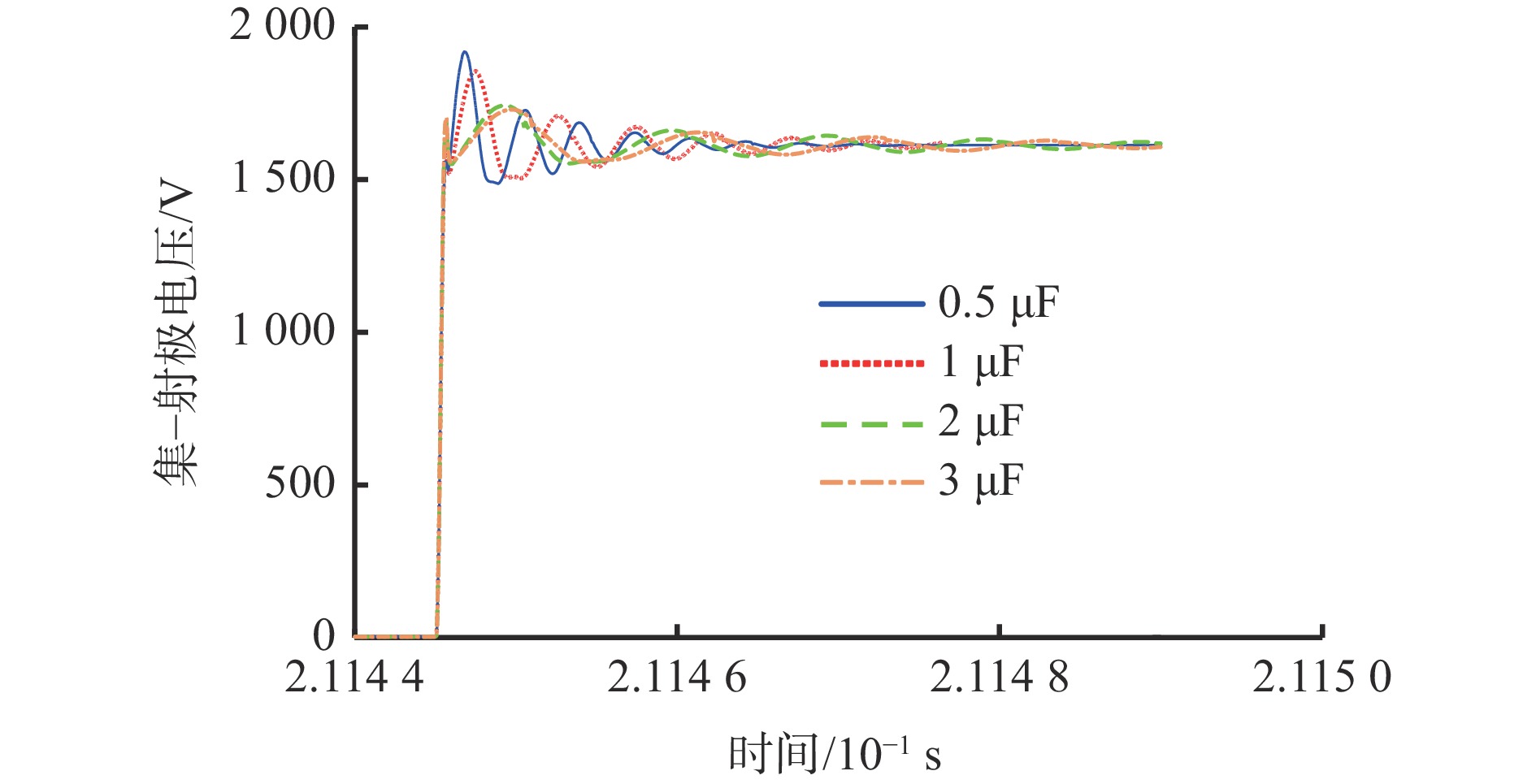
图 14 不同吸收电容时IGBT关断波形
Figure 14. IGBT turn-off waveforms with different absorption capacitances
![]()
图 15 采用吸收电路后栅极驱动电阻、交流母排长度与IGBT尖峰电压的对应关系
Figure 15. Corresponding relationship between gate drive resistance or AC busbar length and IGBT peak voltage after using absorption circuit
![]()
图 16 采用吸收电路后栅极驱动电阻、交流母排长度与IGBT功率损耗的对应关系
Figure 16. Corresponding relationship between gate drive resistance or AC busbar length and IGBT power loss after using absorption circuit
表 1 激励频率为2 kHz时矿用变频器杂散电感
Table 1 Stray inductance of mine-used inverter under 2 kHz excitation frequency
nH LK++ LK−~ LK~+ LK−− LDCU+ LUV+ LVW+ 120 25 96 11 27 30 30 LDC− LUV− LVW− LDC1+ LDC2+ LDC1− LDC2− 40 30 29 24 3 12 19  下载: 导出CSV
表 2 IGBT损耗计算结果
Table 2 IGBT loss calculation results
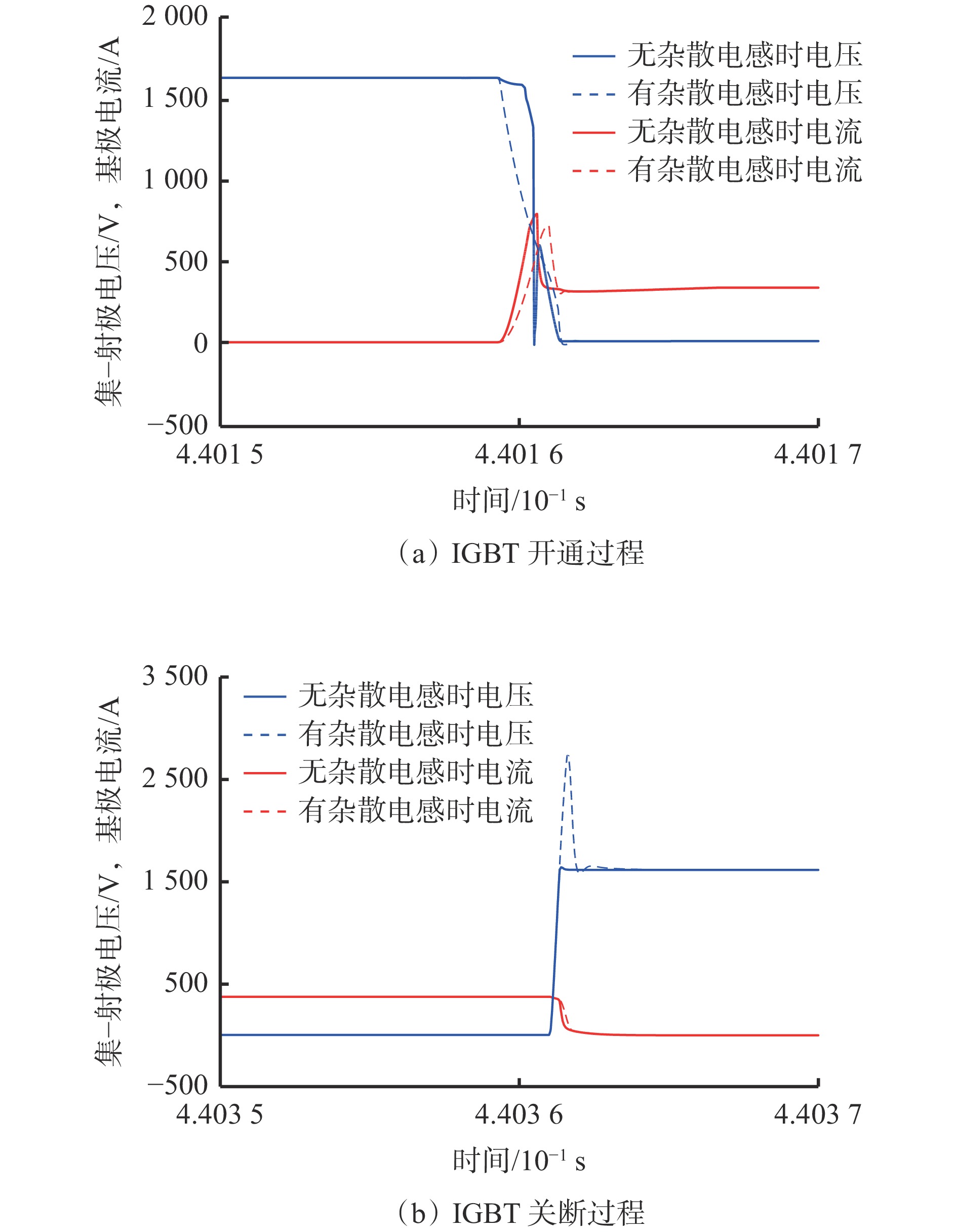
W 条件 开通损耗 关断损耗 导通损耗 总功率损耗 无杂散电感 467 449 687 1 603 有杂散电感 387 694 820 1 901
下载: 导出CSV
表 3 仿真与试验波形的尖峰电压对比
Table 3 Comparison of peak voltages between simulated waveforms and the experimental ones
母线电压/V 尖峰电压/V 误差/% 仿真值 试验值 1 100 1 519 1 485 2.2 1 300 1 768 1 780 0.7 1 500 2 014 2 020 0.3 1 700 2 257 2 181 3.4
下载: 导出CSV
-
[1] 吴传龙,陈伟,刘晓文,等. 基于特征融合的提升机逆变器故障诊断[J]. 工矿自动化,2021,47(5):46-51. DOI: 10.13272/j.issn.1671-251x.17772 WU Chuanlong,CHEN Wei,LIU Xiaowen,et al. Feature fusion based fault diagnosis of hoist inverter[J]. Industry and Mine Automation,2021,47(5):46-51. DOI: 10.13272/j.issn.1671-251x.17772
[2] 唐圣学, 张继欣, 姚芳, 等. IGBT模块寿命预测方法研究综述[J/OL]. 电源学报: 1-29. [2021-12-06]. http://kns.cnki.net/kcms/detail/12.1420.TM.20210802.1742.002.html. TANG Shengxue, ZHANG Jixin, YAO Fang, et al. An overview of lifetime prediction methods for IGBT power module[J/OL]. Journal of Power Supply: 1-29. [2021-12-06]. http://kns.cnki.net/kcms/detail/12.1420.TM.20210802.1742.002.html.
[3] 李方正,孙旭东,黄立培,等. 大容量变流器复杂形状直流母线的PEEC建模[J]. 清华大学学报(自然科学版),2009,49(8):1089-1092. LI Fangzheng,SUN Xudong,HUANG Lipei,et al. PEEC modeling of complex DC buses in high power converters[J]. Journal of Tsinghua University(Science and Technology),2009,49(8):1089-1092.
[4] 陈材,裴雪军,陈宇,等. 基于开关瞬态过程分析的大容量变换器杂散参数抽取方法[J]. 中国电机工程学报,2011,31(21):40-47. CHEN Cai,PEI Xuejun,CHEN Yu,et al. A stray parameter extraction method for high power converters based on turn-on/off transient analysis[J]. Proceedings of the CSEE,2011,31(21):40-47.
[5] 易荣,赵争鸣,袁立强. 高压大容量变换器中母排的优化设计[J]. 电工技术学报,2008,23(8):94-100. DOI: 10.3321/j.issn:1000-6753.2008.08.016 YI Rong,ZHAO Zhengming,YUAN Liqiang. Busbar optimization design for high power converters[J]. Transactions of China Electrotechnical Society,2008,23(8):94-100. DOI: 10.3321/j.issn:1000-6753.2008.08.016
[6] 汪鋆,杨兵建,徐枝新,等. 750 kVA高功率密度二极管钳位型三电平通用变流模块的低感叠层母线排设计[J]. 中国电机工程学报,2010,30(18):47-54. WANG Jun,YANG Bingjian,XU Zhixin,et al. Configuration of low inductive laminated bus bar in 750 kVA NPC three-level universal converter module of high power density[J]. Proceedings of the CSEE,2010,30(18):47-54.
[7] 董玉斐,罗皓泽,杨贺雅,等. 1.2 MV·A混合钳位五电平变流模块的结构布局优化和叠层母排设计[J]. 电工技术学报,2016,31(8):11-18. DOI: 10.3969/j.issn.1000-6753.2016.08.002 DONG Yufei,LUO Haoze,YANG Heya,et al. Engineering design for structure and bus bar of 1.2 MV·A hybrid clamped five-level converter module[J]. Transactions of China Electrotechnical Society,2016,31(8):11-18. DOI: 10.3969/j.issn.1000-6753.2016.08.002
[8] 朱艺锋,郑景乐. 基于结构的变流器母排杂散电感优化方法研究[J]. 机电工程,2017,34(3):293-297. DOI: 10.3969/j.issn.1001-4551.2017.03.016 ZHU Yifeng,ZHENG Jingle. Research on optimization method of stray inductance of converter bus bar based on structure[J]. Journal of Mechanical & Electrical Engineering,2017,34(3):293-297. DOI: 10.3969/j.issn.1001-4551.2017.03.016
[9] 欧阳柳,李华,杨光,等. 风力发电变流器的IGBT关断过电压抑制研究[J]. 大功率变流技术,2012(2):13-15,20. DOI: 10.13889/j.issn.2095-3631.2012.02.011 OUYANG Liu,LI Hua,YANG Guang,et al. Research on suppression of IGBT's turn-off over-voltage for a wind power converter[J]. High Power Converter Technology,2012(2):13-15,20. DOI: 10.13889/j.issn.2095-3631.2012.02.011
[10] 尹新,陈功,沈征,等. 基于栅极控制的IGBT关断过电压研究[J]. 电源技术,2016,40(3):680-683. DOI: 10.3969/j.issn.1002-087X.2016.03.058 YIN Xin,CHEN Gong,SHEN Zheng,et al. Investigation of IGBT over-voltage suppression based on gate control[J]. Chinese Journal of Power Sources,2016,40(3):680-683. DOI: 10.3969/j.issn.1002-087X.2016.03.058
[11] 朱艺锋. 缓冲电容对IGBT变流器特性的影响研究[J]. 河南理工大学学报(自然科学版),2014,33(4):482-485. DOI: 10.3969/j.issn.1673-9787.2014.04.016 ZHU Yifeng. Impact of snubber capacitance on IGBT-converter characteristics[J]. Journal of Henan Polytechnic University(Natural Science),2014,33(4):482-485. DOI: 10.3969/j.issn.1673-9787.2014.04.016
[12] 张承宁,王志福,孙逢春. 基于Pspice的IGBT缓冲电路分析[J]. 计算机仿真,2003(7):107-110. DOI: 10.3969/j.issn.1006-9348.2003.07.033 ZHANG Chengning,WANG Zhifu,SUN Fengchun. An study of the buffer circuit for the IGBT based on Pspice[J]. Computer Simulation,2003(7):107-110. DOI: 10.3969/j.issn.1006-9348.2003.07.033
[13] 张全柱,黄成玉,邓永红. 逆变器用IGBT吸收电路的仿真研究[J]. 电源技术,2009,33(10):914-918. ZHANG Quanzhu,HUANG Chengyu,DENG Yonghong. Simulation research for the IGBT absorbing circuits of inverter[J]. Chinese Journal of Power Sources,2009,33(10):914-918.
[14] 汪波,胡安,陈明,等. IGBT关断瞬态电压尖峰影响及抑制[J]. 半导体技术,2011,36(7):501-504. DOI: 10.3969/j.issn.1003-353x.2011.07.002 WANG Bo,HU An,CHEN Ming,et al. Influence and suppression of voltage spike in turn-off transient of IGBT[J]. Semiconductor Technology,2011,36(7):501-504. DOI: 10.3969/j.issn.1003-353x.2011.07.002
-
期刊类型引用(2)
1. 勾扬. 基于模糊-PID控制的燃机电厂静态变频器自动调速方法. 光源与照明. 2023(04): 141-143 .  百度学术
百度学术
2. 倪少军,于铄航,华程,程卫健. 基于PIMC-STATCOM的低压配电网电能质量治理. 供用电. 2023(11): 76-83 . 百度学术
其他类型引用(1)
计量
- 文章访问数: 175
- HTML全文浏览量: 40
- PDF下载量: 27
- 被引次数: 3
